Numerical Investigation of Particle Packing and Flow Dynamics in Fixed Bed Reactors
A comprehensive computational investigation integrating DEM and CFD to evaluate the hydrodynamic and thermal performance of packed bed reactors using hollow cylindrical and trilobe-shaped catalyst pellets.
- Max Mesh Size
- 140 million cells
- Gas Inlet Temp
- 300 K
- Particle Wall Temp
- 1300 K
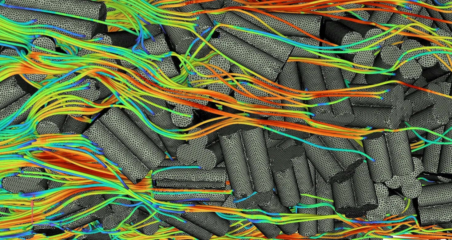
Motivation
Fixed-bed reactors play a critical role in large-scale sustainable chemical processes, such as methanol synthesis from and , and Fischer-Tropsch synthesis. Traditional pseudo-homogeneous models often fail to capture microscale phenomena like wall effects, channeling, and localized thermal gradients. This project utilizes particle-resolved computational models to explicitly resolve actual pellet geometries within the packed bed, enabling highly detailed analysis of fluid flow and heat transfer at the particle scale.
Methodology
- Domain & Geometry: Realistic packed beds were generated using ANSYS Rocky DEM, where custom-shaped pellets (hollow cylinders and trilobes) were introduced via gravity-driven filling to simulate realistic random distributions.
- Meshing: High-quality unstructured tetrahedral meshes were generated using ANSYS ICEM CFD. The meshes resolved narrow interstitial gaps between particles, with final grid sizes reaching up to 140 million cells to ensure grid independence.
- Simulation Automation: ANSYS Fluent was utilized to solve the fluid dynamics, with the entire workflow—from mesh importing to boundary condition assignment and data extraction—automated via PyFluent scripts.
- Boundary Conditions: For thermal modeling, the energy equation was activated. The gas phase entered the reactor at 300 K, while the particle surfaces were assigned a constant wall temperature of 1300 K.
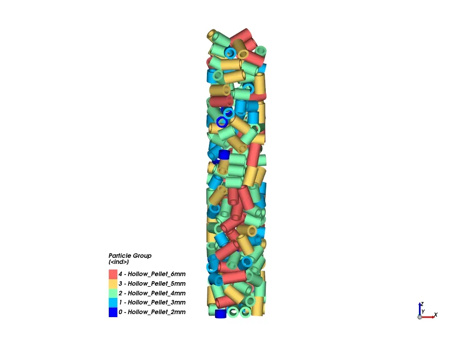
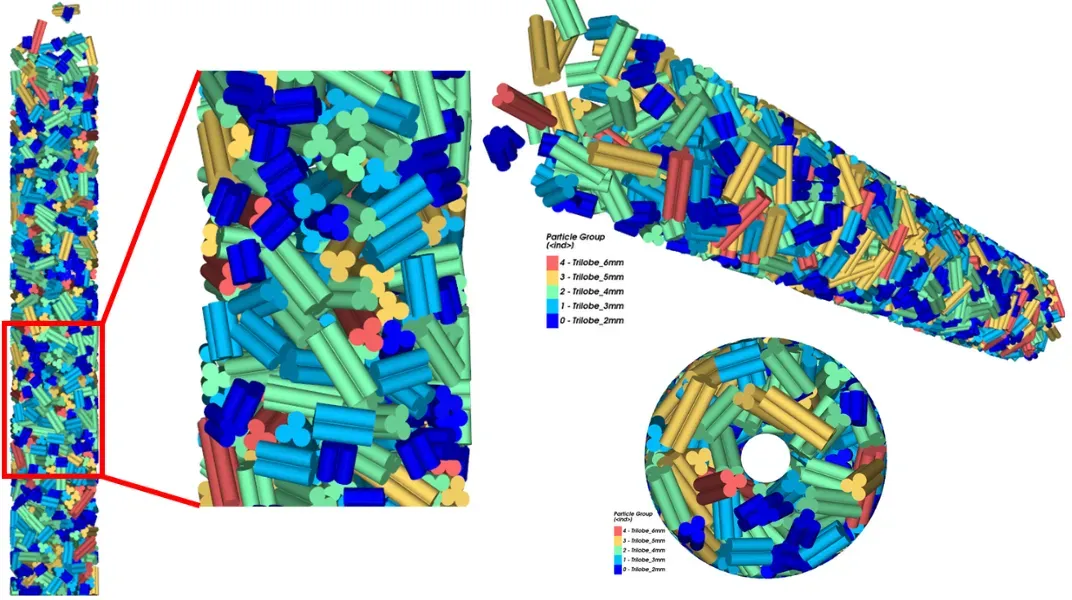 Figure: DEM-generated packing structures for hollow cylindrical and trilobe pellets
Results & Analysis
The integration of DEM and CFD provided critical insights into the hydrodynamic and thermal behavior of the reactor.
- Pressure Drop: CFD pressure drop predictions aligned closely with analytical estimations from the Ergun equation. The Ergun equation represents the pressure loss as:
- Experimental Deviation: Experimental pressure drop measurements were systematically higher than both CFD and analytical models, primarily due to real-world pellet deformations (bending) and non-ideal packing that increased flow tortuosity.
- Flow Heterogeneity: Hollow cylindrical beds exhibited relatively uniform pressure and velocity fields, whereas trilobe pellets induced localized high-velocity channeling and heterogeneous pressure gradients.
- Thermal Performance: Lower mass flow rates led to rapid gas heating within the initial sections of the bed due to longer residence times.
- Geometry Impact: Trilobe pellets demonstrated enhanced heat exchange capabilities compared to hollow cylinders because of their increased surface area and the creation of more complex flow paths.
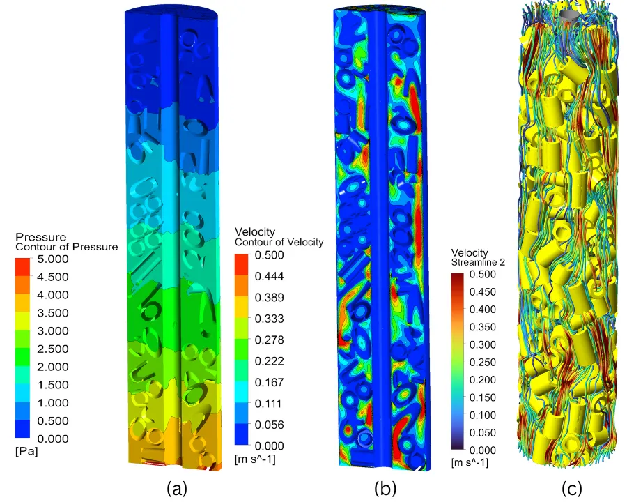
Hollow Cylinder: Velocity Streamlines & Pressure Contours
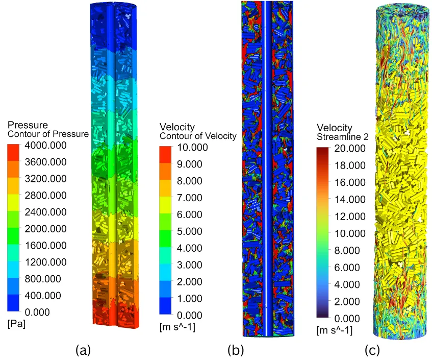
Trilobe Pellets: Velocity Streamlines & Pressure Contours
Related Projects
Numerical Investigation of Flow Past a Circular Cylinder using OpenFOAM
Development of a fully parameterised, block-structured meshing and automated simulation framework for incompressible bluff-body flow analysis in OpenFOAM.
On the Hydrodynamics of Foiling Craft: PID Control System Development
Development of a coupled CFD-PID control framework to regulate hydrofoil angle of attack for stable ride height and trim under steady, unsteady, and multiphase flow conditions.